When you buy through links on our site, we may earn an affiliate commission.


GenTLe
-
Posts
1,973 -
Joined
-
Last visited
-
Days Won
9


GenTLe's Achievements
")


-
Once you've seen that the movement performs normally, you can finish it with the rest. Therfore rotate the movement and we'll start with the bits on top! Not a lot of pics here as the process is quite straightforward. Anyway install in this order: "CANNON PINION WITH DRIVING WHEEL 028-A16", then together the "24HOUR WHEEL 103-A16" (103-A09 in the PDF) and the "MINUTE WHEEL AND PINION 072-998", and finally the other smaller gears: "INTERMEDIATE DATE CORRECTING WHEEL(1) 087-A71", "INTERMEDIATE DATE CORRECTING WHEEL(2) 087-A75", "CALENDAR CORRECTOR WHEEL 213-614" and the "INTERMEDIATE DATE CORRECTING WHEEL 087-A72": It's now the time for the 2 springs (named respectively "Date jumper 109-875" - 109-870 in the PDF; and teh "CALENDAR CORRECTOR LEVER SPRING 903-A17"), one acting on the date wheel and one for the "INTERMEDIATE DATE CORRECTING WHEEL 087-A72", plus you put the "Hour wheel 075-A51" with its copper washer and finally also the date wheel/disk: Note: if you don't manage to make the "Date jumper 109-875" - 109-870 in the PDF - to stay in place, you can fix it later: there's a small hole in the top plate to fix it. Finally the top plate "DATE INDICATOR MAINTAINING PLATE / HOUR WHEEL SPRING 176-A04" with its 5 tiny screws: Test that the stem works fine, that you can manually wind the movement, set the time and quick change the date. Test also that the date changes automatically moving the time forward in the time setting position. If all is fine, regulate the movement, and as very lastly put back the autowind rotor and you've done! Here the results after the service (remember it was running with 166° amplitude before...): Face up: Crown at 3: Crown up: Crown at 9: I may say that I'm pretty satisfied of the results, also because I've never seen a 9015 going up to more than 300° of amplitude! I think that the initial problem was simply that the main barrel got opened: it is visible by how the main spring was not plain in the open barrel picture, plus when I disassembled the movement I found it open...
-
Let's start with the rest. A premise: this is the way the main spring goes into the barrel, as reference (picture taken while disassembling it, quite dry as you can notice...): Once the plate has been rotated, you can install the "Complete barrel 001-992" but, before, install the click and its spring ("Click 060-551" and "Click spring 903-A15") with their screws and the "Breaklever for second hand 269-402" which is the one that hacks the watch when you put it in time-setting mode. Respectively 1, 2 and 3 in the pic below. Another suggestion is to have the click spring slightly lifted so that it doesn't push on the click. You will put it back later once the top plate "BARREL AND TRAIN WHEEL BRIDGE 701-J09" has been installed (there's a hole to fix the click in that), otherwise installing the top plate is a mess... Once done, you can put the "RATCHET WHEEL 059-802" on top of the barrel, the "CENTER WHEEL & PINION 012-A20" and finally the "Reversing wheel 141-251" (that I treated with Lubeta reversing wheels lubricant in advance): Then up it goes the "Center wheel bridge 702-201". Remember to put some Moebius HP1300 in the jewels that will support the other gears on top of the plate, as once the bridge has been installed those jewels in it will face the main plate and will not be reachable: And here we are with those "other gears on top of the plate" that I mentioned at the previous point: the "INTERMEDIATE REDUCTION WHEEL AND PINION(2) 088-252" and the "INTERMEDIATE REDUCTION WHEEL AND PINION(3) 088-253". Also the "Escape wheel and pinion 032-991" has been placed in its jewel: Finally you install the rest of the main train wheels: the "Third wheel and pinion 017-A01" (check that the lower pinion is correctly in its jewel!!!) and the "Fourth wheel and pinion 023-A21". Do NOT install the pallet fork and its bridge ("JEWELED PALLET FORK AND STAFF (9015-26A) 035-701" and "PALLET BRIDGE 708-091") now like in the picture. Leave it for later!: Now put all this on a side as we have to assembly all the parts composing the "BARREL AND TRAIN WHEEL BRIDGE 701-J09". Similar to the ETA 2892 parts of the autowinding system are hidden below of this bridge and require assemblage before to install the bridge on the rest of the movement. I will show a couple of pictures so that you can see how it is composed. The first is when it has been disassembled, the second with all its parts in place. The parts are the "TRAIN WHEEL GUARD(MANUAL- WINDING) 117-361" (117-360 in the pdf assembly schema) which keeps in position with 3 tiny screws the gears named "RATCHET SLIDING WHEEL(2) 087-A74", "RATCHET SLIDING WHEEL(1) 087-B08" (087-B03 in the pdf) and the "CROWN WHEEL 058-501" Plus the "TRAIN WHEEL GUARD(AUTOMATIC) 117-354" that keeps in place the gear named "INTERMEDIATE REDUCTION WHEEL AND PINION(4) 138-251" Now the trickiest part is to place the "BARREL AND TRAIN WHEEL BRIDGE 701-J09" because, as you can see from the previous picture, you will need to align 6 pinions plus the barrel arbor... Not exactly immediate... But anyway with patience you can do it. Do NOT push the plate, it will not go in place in that way and you'll damage the pinions! When it seems in place, put a pair of screws without tighten them and try to rotate the barrel with a finger or something: the wheels should rotate freely without too much pressure. Also now it's time to fix the click spring through the hole at 11 o'clock in the picture Now you can fit "JEWELED PALLET FORK AND STAFF (9015-26A) 035-701" and "PALLET BRIDGE 708-091" (not yet installed in the picture), other than the "INTERMEDIATE REDUCTION WHEEL AND PINION(1) 088-251" with its spring clip (take care: that spring clip tends to fly away landing in "that place where the watch movement bits disappear") You can now finally put the balance and its bridge and test the movement and see if it works fine, before to start the final part (time setting and date wheel mechanics). END OF SECOND PART
-
Hi Mates, within my researches I've never been able to find a proper step-by-step Miyota 9015 assembly tutorial online, and neither an oiling chart for it. I hope this thread will unveil it for a larger public and will be a kind of reference for those that will have to deal with this movement. It all started when I got this watch, a BP factory 16613 sub. A very nice watch with a Miyota 9015 inside (I chose the "undecorated version" of it, as it's a closed case back watch and I value reliability and ease of access more than a fake plate glued on top) with a blue sun-ray dial (with purplish reflexes that came ONLY in the pictures I take with the phone, and totally plain blue at naked eyes). This one: It worked fine for like 3 days after I regulated it, then I noticed it started to misbehave, loosing even 5 minutes/day... So I put it on the timegrapher discovering something very wrong with it... The amplitude was ridiculous and the power reserve was very bad (normally these movements should be around 270° when fully charged): Since I never put my hands on a 9015, I decided to buy a new movement for a quick swap, as I don't like to have a watch disassembled for too much tim. I got it from here: https://www.ebay.com/itm/142324061467 but at the time I bought it, it was priced at 76US$... So a good price. Now it's too expensive there, better on Cousins UK. The only difficulties I had in the swap were caused by the tiny screws of the "DATE INDICATOR MAINTAINING PLATE / HOUR WHEEL SPRING 176-A04" which were partially hidden below the date wheel overlay added to center the date in the date window and to give it the correct fonts and date disk base colour. With patience it is feasible anyway. After some time I took the bad working movement and started to deal with it. To help my job this document http://www.citizen.co.jp/miyota_mvt/9015/pdf/parts_9015.pdf was very important, as like as the camera pictures that I took disassembling it which I used as references sometimes. Also take a look to this as the terms I'll use will be taken from it: http://miyotamovement.com/parts_search.php?open=9015 So, let's start with the movement in bits, after the cleaning process. Respect to the ETA ones with same functions (2824, 2892 etc) this movement is more complex: it has more parts and the assembly can be a bit tricky, as for instance the "barrel and train wheel bridge" requires to align 6 pinions (vs. 4 for the 2824 and 3 for 2892), so not exactly something immediate, but anyway it is something that can be done. My suggestion is, as always, to divide the parts in functional groups while you're disassembling the movement, marking how you divided them on a paper copy of the assembly chart pdf file I placed upper in this post. Each functional group and its screws goes into a different container (keeping that separation also when washing the bits) in order not to mix them up. There are several similar gears and screws, which by the way are NOT identical, so take care not to mix them. Also you need to take care reassembling the Miyota version of the balance shock absorber. The first time I did it I put the "Spiral spring with jewel 098-090" upside down, leaving the concavity (which I thought was for the oil) to the external side, and having the balance blocked due to the interference between it and the spiral spring jewel itself. THIS is the way to correctly install it, the "Spiral spring with jewel 098-090" is the yellow part indicated with B and has the concave side of the jewel facing the balance: Now let's get back to the movement assembly. I'll not go into the details of the oiling: once you've done it for few ETA ones, you'll understand which oils / greases and where to put them by your experience. This is the main plate, already with the antishock installed but with nothing else on it: As usual I start the assembly from the keyless and stem parts. To do that, you need to rotate the plate in order to ease the insertion of the stem and the "clutch wheel 064-991" and the "winding pinion 063-351": Here a close up of the clutch wheel 064-991" and the "winding pinion 063-351" with a mixture of Moebius HP 1300 and some Molycote DX (lithium and PTFE based white grease): Once the stem is correctly in, then you can rotate again the plate, as the rest of the keyless parts are on the other side. I treated them (all and the stem too) with some Moebius Fixodrop to avoid oil to spread around. Starting the assemblage of the keyless, the first bit is the "Setting lever 067-995": Followed by the "Yoke 071-995" (note that it acts as a spring, so the final part of it presses against the protrusion at the border of the main plate): On top of both there is the "Operating lever 257-152": And finally the "Setting lever spring 077-996". I suggest to put it and start to screw its 2 screws while the spring is not yet engaged with the "Setting lever 067-995". Stop to screw-in when there is a minimum of resistance, make the spring part to fit on the setting lever protuberance and finish to tight the 2 screws. I also installed the "Setting wheel 076-751" (that small gear at the top of the operating level): put some oil on its post so that it doesn't fall whan you rotate the movement to go on with the installation. END OF FIRST PART
-
Actually I measured the retaining ring on my V3 and V5 Noob and the right size of the die should be 30.5mm (internal). It can't be 29.5 as that is the internal diameter of the gasket, and you need to press a ring which is placed outside the external part of the gasket.
-
Thanks to botsyboy (RWI) I got the size: 29.5mm, on CousinsUK it's the R30520 THe fact is that the crystal of rolexes are smaller in the hidden part, so even if outside it is a 30.4mm, then below it's a 29.5. See a Milgauss one for example:
-
You can try to contact him. The mail is wilerwetta AT gmail DOT com
-
I have a couple of Noob subC, a hulk v3 and a black V5 (and also a BP PRoHunter GMT 2). Measuring the diameter of the crystal, without taking it out, I read around 30.4mm, so I suppose it is a 30.5mm as normal for a Noob one. May someone help me to get which is the right one 2.3mm tall to select? At cousins, if I check in the "Rolex non branded" parts, I can select up to 29.6mm (internal) size: https://www.cousinsuk.com/product/glass-gaskets-iso-swiss-additional-sizes or 29.5mm: https://www.cousinsuk.com/product/glass-gaskets I'm a bit lost... Thanks in advance! GenTLe
-

Lubricating ETA time/date movement reverse gears - HOW TO
GenTLe replied to GenTLe's topic in Watch Repair & Upgrade
Thanks Rolexman! I found out that one of the best cleaning way is warm isopropyl alcohol (put some hot water in the ultrasonic cleaner and a little jar with the alcohol, bain-marie way) and give a full 5min ultrasonic shake -
Scam site. Noob factory does NOT have any website. They are just pretending to be them. And, by the way, they are at v7 now. Look for the v7 sub on any of the TD site like InTime01.co or tb-688.com
-
New Seiko Turtle with domed aftermarket blue AR sapphire crystal. And good beers
-
tb-688.com Yes but they still have made them wrong colour
-
Look what arrived at Toro (not yet on his site): Waiting to see the price. It could me my next watch. I love that vibrant yellow
-
Probably this one:
-
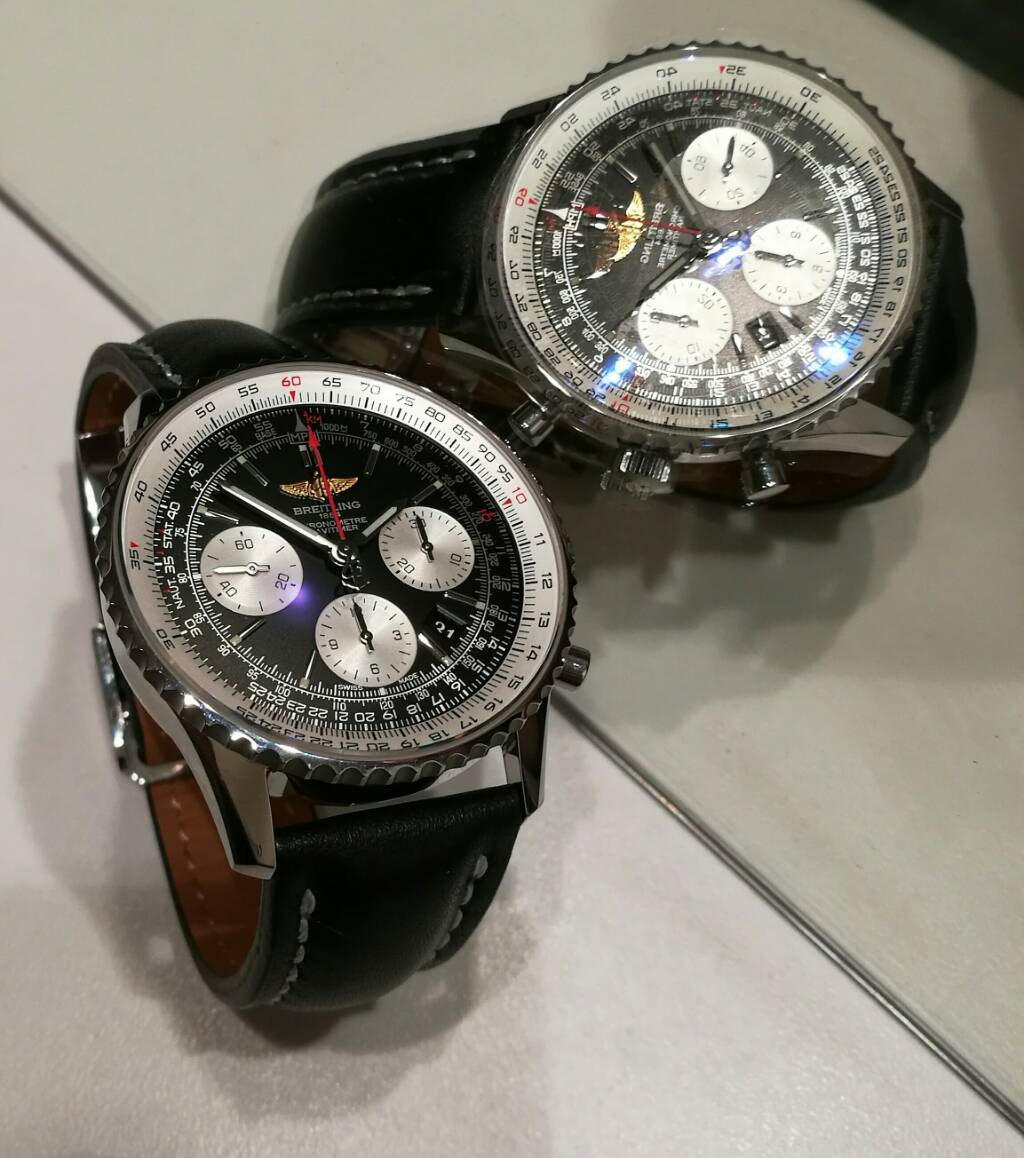
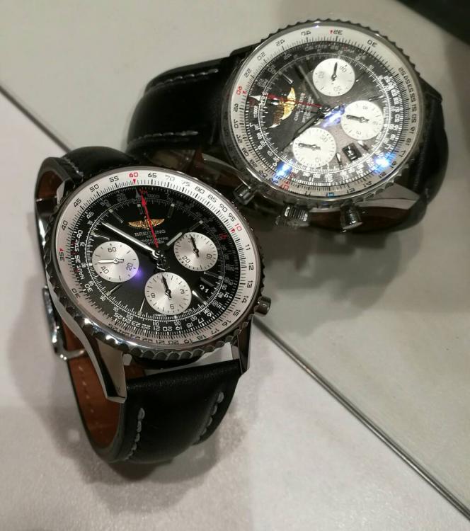
Congrats! Probably the same I am waiting This is mine: http://iwatchstation.com/navitimer-01-11-ss-black-dial-on-black-leather-strap-a7750.html Inviato da mTalk