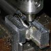
jmb Posted January 31, 2010 Report Posted January 31, 2010 Now that Lani came through with a loaner MBW 5513 retention ring I can make a couple to replace those of Kurt's that the postal service swallowed! I priced some 316L and decided that there was absolutely nothing wrong with 303 in this case since nobody will see it. I first measured the loaner ring and made a working drawing (attached in PDF format). I then chucked up a scrap of 1 7/16" round 303 in the lathe and turned about 1/4 inch to proper OD: Then drilled a hole that a small boring bar would fit through: After the hole was drilled through it was time to bore the ID to size. This needs to be held pretty close tolerance as this dimension determines how much squeeze is gonna get put on the crystal to case junction: I chose to machine this .001" undersize as I have noticed varying diameters in aftermarket crystals. If too tight then the ID can be sanded a bit until you have a perfect fit: I then mounted the cutoff tool and machined in the "step" and parted off the ring: Here is the finished product. Original ring on the right: I probably won't machine the rest of them until I finish the toolholder for my carbide cutoff blade as it will leave a better surface than the "flexy" cobalt steel blade and be easier to control precisely. I feel that I just got lucky on this one with the cobalt blade! Well, that's all there is to it. Small Chinese lathes are not all that expensive and with a couple mods and upgrades can hold pretty fair tolerance so go get one and have fun!! MBW 5513 Retention Ring.pdf
Bike Mike Posted January 31, 2010 Report Posted January 31, 2010 Whooohooo...now you are talking my language! Nicely done! What kind of lathe is that? Been looking at getting a bench top one for home to do work like this.
jmb Posted January 31, 2010 Author Report Posted January 31, 2010 It's a cheapie Chinese 9x20. This one is a Harbor Freight branded one but you can get the same one branded as Grizzly, Enco, Jet, etc. The stock compound clamp needs to be replaced with a beefier one (homebrew) and I then installed a quick-change toolpost and a 1.5 HP variable speed DC drive motor. I got it on sale several years back and I think with all the mods still have under $1k invested in it,
redwatch Posted January 31, 2010 Report Posted January 31, 2010 You guys will always amaze me!!!! I would love to learn metal working!!! I love precision engineering and manufacturing and this would be right up my alley with electronics and soldering and prototyping.
TeeJay Posted January 31, 2010 Report Posted January 31, 2010 Nice work, bro, my dad was a tool-maker by trade, and it's always fun to see the tools in operation
Justasgood Posted January 31, 2010 Report Posted January 31, 2010 Here is the finished product. Original ring on the right: Notice in this picture (above) ... the ring on the right has a gap between it and the table. There is a slight bevel from the undeerside that allows the bezel to rotate when pushed down. Justin, Thanks so much for taking on this to help me and others out. Note: Look closely at the loaner underside. There is a slight thinning or bevel on the edge that allows the bezel to turn freely when pushed down. You may have it but in your pictures it is hard to tell. Use a micrometer and measure fron the inside(nearest the crystal) and pull it outward toward the edge and you should notice a thinning right at the very edge. Thanks again and thanks To Lani for the loaner.
freddy333 Posted January 31, 2010 Report Posted January 31, 2010 Great work. In addition to Justasgood's comment about the beveling, I wonder if the thickness (height) is the same? I assume you calp'd that dimension, so maybe it is just the way it appears in the pics?
Tribal Posted January 31, 2010 Report Posted January 31, 2010 Great work. A lathe is really great to have I shaved the bezel from my old MBW in the past to fit a gen insert.
jmb Posted January 31, 2010 Author Report Posted January 31, 2010 overall height is the same on this but looks thicker, probably 'cause no bevel. This one goes to the scrap bin and I start over!
jmb Posted February 1, 2010 Author Report Posted February 1, 2010 Corrected drawing to reflect "bevel" and added bevel detail.
Justasgood Posted February 1, 2010 Report Posted February 1, 2010 Corrected drawing to reflect "bevel" and added bevel detail. J, Look at the underside as well........it should also bevel a bit. There has to be room for the bezel to push down and clear to turn. Kurt.
jmb Posted February 1, 2010 Author Report Posted February 1, 2010 The detail in the corrected drawing shows the bevel I measured. I've sent some to a respected source to see if what I have done so far will work with the bezel as I don't have one to try them with...
ubiquitous Posted February 11, 2010 Report Posted February 11, 2010 The detail in the corrected drawing shows the bevel I measured. I've sent some to a respected source to see if what I have done so far will work with the bezel as I don't have one to try them with... Tested and confirmed. I believe we are a go!
Justasgood Posted February 11, 2010 Report Posted February 11, 2010 Tested and confirmed. I believe we are a go! Serious? That is awesome!!!!!
lanikai Posted February 12, 2010 Report Posted February 12, 2010 That's great J.. please shoot the loner back as soon as you can.. I gotta return it to someone else.. AC/Lani
jmb Posted February 12, 2010 Author Report Posted February 12, 2010 Crap, OK! Hell, I wuz fixin' to e-Bay it!! This weekend I'm going to try to turn out a couple more this weekend and I'll return the loaner and a couple spares for your trouble first of next week. Remind me not to forget to make a couple for Kurt!
jmb Posted February 12, 2010 Author Report Posted February 12, 2010 Thanks, R, it's nice to see exactly how this mates up with the other part!
Recommended Posts
Create an account or sign in to comment
You need to be a member in order to leave a comment
Create an account
Sign up for a new account in our community. It's easy!
Register a new accountSign in
Already have an account? Sign in here.
Sign In Now