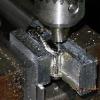
jmb Posted April 6, 2010 Report Share Posted April 6, 2010 OK, now that "the watch" is no longer a secret I'll outline how I did the solid lug bar conversion. I'm no expert but this procedure is what I came up with and it seemed to make sense to me. When Ubi started "the project" he asked if I would like to take a stab at converting a case he was using to solid lug/strap bars ala 5513. I said, "Sure, worse that could happen is that I totally screw it up!" The case was then in the mail... I contacted Toomuchgear, as he has a really nice example of one of this style, and he took some measurements and supplied the diameter of the bars which turned out to be 1.75mm. After running through all of the usual (and not so usual) places I order material from the closest I could get was 2mm. No prob, I thought, I'd just turn 'em down a bit. Being so small it would be necessary to use a "follow rest" on the lathe to keep the skinny little $hit from bending. Not a problem, I remember getting one with my lathe - yeah, right, good luck finding it! Since I've had the lathe for 4-5 years, and never had the need to use the rest, it took me about half a day of looking but I finally found it and attached it to the lathe. The follow rest needs to be adjusted to provide backup behind the piece where the cutting tool contacts the work to eliminate any flex. If you don't do this the diameter would not be constant and most likely the stock would be bent. Here's a pic of the rest installed and adjusted. I won't bore you with pictures showing me reducing this down to 1.75mm... I then turned my attention to the case. I clamped my "fixture" into the vise on my mill and clamped the case to it. In these shots the clamp has been omitted so as to not obscure any details, just "visualize" a clamp securing the case. I then used a conical edge finder to locate the center of the hole, switched to the proper sized bit and enlarged the hole. After drilling the case I then cut a couple pieces of the now 1.75mm rod long enough to fit and have plenty of extra to blend in. I then made sure the pins would fit tightly into the holes, some light polishing was required to achieve a nice tight fit. The fit was such that they needed to be tapped in with a hammer so I was satisfied. I then removed the pins, applied clear epoxy into the holes, and drove the pins home. After the epoxy had time to cure I then took the assembly to the bench grinder and roughed them to length and shipped everything back to Ubi for final grinding and polishing. That's all there is to it. Hopefully some of you will enjoy the blow-by-blow accounting of this phase of the project. Quote Link to comment Share on other sites More sharing options...
ubiquitous Posted April 6, 2010 Report Share Posted April 6, 2010 Always fascinating to see the behind the scenes stuff! Great work, jmb! Now I know what went into getting those bars to work! Quote Link to comment Share on other sites More sharing options...
Justasgood Posted April 6, 2010 Report Share Posted April 6, 2010 Impressive J. I really do appreciate all the trouble everyone involved with this project went through. If any of you make it up to or around Nashville, Drinks are on me. Quote Link to comment Share on other sites More sharing options...
rosnik Posted April 6, 2010 Report Share Posted April 6, 2010 Nice! My compliments. Quote Link to comment Share on other sites More sharing options...
redwatch Posted April 6, 2010 Report Share Posted April 6, 2010 Sweet pictorial J! Like Ubi I am always fascinated and intrigued by the "behind-the-scenes" work done in this hobby! Quote Link to comment Share on other sites More sharing options...
jmb Posted April 6, 2010 Author Report Share Posted April 6, 2010 K, not a problem, it was fun working on this and every project I do I learn a little more... Quote Link to comment Share on other sites More sharing options...
tmg Posted April 6, 2010 Report Share Posted April 6, 2010 Great post JMB! Congrats on the watch too K -she's a beauty. Quote Link to comment Share on other sites More sharing options...
FxrAndy Posted April 6, 2010 Report Share Posted April 6, 2010 I like the drilling jig i think i would like to make another like the one i have but from a teflon block Quote Link to comment Share on other sites More sharing options...
alligoat Posted April 6, 2010 Report Share Posted April 6, 2010 Nice job, JB! It's always cool to see how a 'pro' does it! Quote Link to comment Share on other sites More sharing options...
HauteHippie Posted April 6, 2010 Report Share Posted April 6, 2010 Great walk through, and the rest is history as they say... Quote Link to comment Share on other sites More sharing options...
rolexmaniac88 Posted April 6, 2010 Report Share Posted April 6, 2010 Great post! I wouldn't have guessed it was done like that so very informative post indeed! jmb you may have a pm soon and you may also already know why ! Quote Link to comment Share on other sites More sharing options...
ismaelmv Posted April 6, 2010 Report Share Posted April 6, 2010 This is very amazing info. I'm also loving this behind the scenes stuff. Quote Link to comment Share on other sites More sharing options...
stilty Posted April 6, 2010 Report Share Posted April 6, 2010 Great post! I have a feeling you may be getting a lot of requests for lug drilling. Quote Link to comment Share on other sites More sharing options...
jmb Posted April 6, 2010 Author Report Share Posted April 6, 2010 I just ordered a couple dozen more drill bits... :-p Quote Link to comment Share on other sites More sharing options...
vlydog Posted April 6, 2010 Report Share Posted April 6, 2010 Great idea for the jig and thanks for posting this process. Quote Link to comment Share on other sites More sharing options...
TeeJay Posted April 6, 2010 Report Share Posted April 6, 2010 Always a pleasure seeing shots from the Mod Shop Quote Link to comment Share on other sites More sharing options...
dluddy Posted April 7, 2010 Report Share Posted April 7, 2010 Wonderful project for a top notch bloke. Enjoy that one K Quote Link to comment Share on other sites More sharing options...
chubbchubb Posted April 7, 2010 Report Share Posted April 7, 2010 Very nice.... Quote Link to comment Share on other sites More sharing options...
Brightight Posted April 7, 2010 Report Share Posted April 7, 2010 Great pictorial, I just love stuff like this, dreaming of when I can sneak a lathe in past the wife.......... and learn how to use it beyond the simple stuff I've done in the past! Quote Link to comment Share on other sites More sharing options...
vafarmer70 Posted April 7, 2010 Report Share Posted April 7, 2010 Very nice, thanks for sharing. Since you are local, I may have to pop in and see this machine work up close Quote Link to comment Share on other sites More sharing options...
eddog Posted April 7, 2010 Report Share Posted April 7, 2010 Awesome JMB!! It always amazes me when people make projects like this so logical and possible... Thanks for letting us in on the process! Cheers Eddog Quote Link to comment Share on other sites More sharing options...
omgiv Posted April 7, 2010 Report Share Posted April 7, 2010 Thanks for all of the information and pictures. You have inspired me to do a 5517 project (yet another project :rolleyes: ) Thanks!!!! Quote Link to comment Share on other sites More sharing options...
jmb Posted April 7, 2010 Author Report Share Posted April 7, 2010 Once can never have too many projects, right? Quote Link to comment Share on other sites More sharing options...
vlydog Posted April 7, 2010 Report Share Posted April 7, 2010 Once can never have too many projects, right? or have too much fun Quote Link to comment Share on other sites More sharing options...
Tribal Posted April 7, 2010 Report Share Posted April 7, 2010 Great work, really impressive. I Know how hard it is to drill the holes well centered. Yours Look Great. Quote Link to comment Share on other sites More sharing options...
Recommended Posts
Join the conversation
You can post now and register later. If you have an account, sign in now to post with your account.